
Most drivers probably think turning signals is as easy as pushing a lever up or down to make them flash. However, there is some nifty technology at play. This article will teach you the knowledge behind and how to wire a turn signal flasher.
Table of Contents
- What is a Turn Signal Flasher?
- Types of Turn Signal Flashers
- How do Turn Signals Work by thermal flasher?
- Symptoms of a Bad Turn Signal Relay
- How to Test a Turn Signal Relay
- How to Wire a Turn Signal Flasher: Replacement of a Faulty Turn Signal Relay
- How to Wire a Turn Signal Flasher: Further Troubleshooting
- Conclusion
What is a Turn Signal Flasher?
The turn signal flasher turns on the indicator lights every time you take a right or left turn. This electrical component acts like a relay that blinks while you move the knob. It tells the drivers behind you about your turn intention so that you do not abrupt the traffic.

Caption: Lights of a car
Types of Turn Signal Flashers
There are four types.
- Mechanical: These flashers have mechanical switches to turn on the signal bulbs. Mainly they have bimetallic strips and heaters in older cars.
- Electronic: Electronic flashers work on the amount of current passing through a turn signal relay bulb and simultaneously turn them on and off.
- Thermal: The improvised version of the mechanical flasher, the thermal flasher, heats the bimetallic strip. With its help, the current flows in the whole system.
- Solid state: Modern cars hold a solid-state mechanism to turn light signals on. It uses computer chips to regulate the flow of current within the system.
How do Turn Signals Work by thermal flasher?
Nowadays, thermal relays are the most common in the market.
How are turn signals wired?
When the key is in the on position, electricity flows through the circuit that controls the turn signals. The power source for the thermal flasher is a fuse box. The connection is then made to the stalk located on the column.
The signal switch either cuts power or sends it to the left and right indicator light, depending on where the turn-signal stalk is. The lights get their juice from the power outlet, travel through the filaments, and then go straight to the ground wire.

Caption: turn-signal circuit
Source: https://auto.howstuffworks.com/
However, the turn-signal circuit with a Two Prong Automotive Flasher and the one with a Three Prong Automotive Flasher have differences.
Two Prong Automotive Flasher Wiring Diagram
These basic signal lights are heated to function. The Bi-Metalic switch opens and closes as the circuit is completed, heating a small heating coil.
Turn signals complete the circuit and supply the necessary current to activate the lights. Since electricity is only being supplied to the heating coil (a high-resistance load), the light bulbs will not illuminate.
The switch will close quickly since the temperature will rise. As soon as it snaps shut, it cuts electricity to the heater and turns on the lights. When the temperature drops, the switch reopens, and the lights go out. This loop will continue if the toggle is not set to the middle position.
Three Prong Automotive Flasher Wiring Diagram
The 3 Terminal (or prong, sometimes called) flasher operates similarly to the 2 Terminal flasher. It is merely a collection of connections that, when closed, illuminate a single dashboard indication lighting. It performs the same function as before but with an additional terminal denoted by the letter ‘P.
If that light is an LED, it might come in handy. If used as a standalone-dedicated flasher, I can also see this being useful for an Emergency flashing lamp. Nonetheless, the ‘P’ terminal can often serve the same purpose as a direct connection to the ‘L’ terminal.
Keep in mind that the heater connection means the ‘L’ terminal would still have little power on it, which could cause problems if it needs to be turned off; in this case, a three-terminal flasher would be useful the ‘P’ terminal could be used instead.
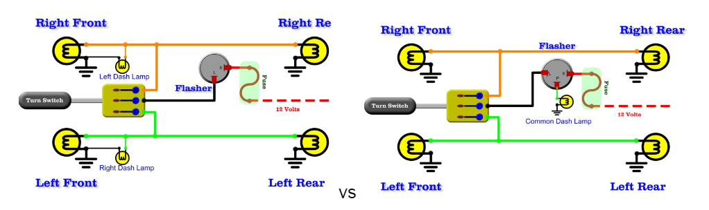
Caption: 2-Pin Electric Flasher Relay vs. 3-prong flasher setup
Source: http://www.gtsparkplugs.com/flashers-turn-signal.html
Flasher Wiring Diagram with Emergency Flasher
A switch for an emergency flashing light has been added to the standard 2-terminal wiring design. The emergency switch functions similarly to a Single Pole Double Throw (SPDT) switch, simultaneously activating both the left and right sides. When the panic button is pressed, all of the lights will flash.
There is nothing particularly miraculous about this. Turning the steering wheel to the left or right will have no effect if your emergency flashers are on. Aside from that, it’s just a simple circuit to get you started and familiar with the principles at play here. Due to the complex nature of modern vehicle wiring, most automakers take a more involved solution to this problem.
Understanding the operation of these basic auto flashers should provide you with no excuse for not completing the wiring. The good news is that most auxiliary harnesses already include these features.

Caption: Flasher Wiring Diagram with Emergency Flasher
Source: http://www.gtsparkplugs.com/flashers-turn-signal.html
How does the thermal flasher work?
Thermal flasher components include:
- A wire contact that carries current
- A softly bent piece of coil spring
- Wrapping resistive wiring on coil spring
The turn-signal device links the thermal flasher to a turn-signal light when the stalk is lowered. Completing the circuit allows current flow. The resistor draws electricity before the spring steel touches the contact. The resistive wire heats the spring metal and switches the switch lights.
The tiny chunk of coil spring heats up and straightens the wider, curved piece in just a second. That presses the curved spring metal into the junction so current flows unobstructed to the signal lights. Without much current, the resistor’s steel wire cools, bends away from the contact, and breaks the circuit. Repeat. 1-2 times per second.
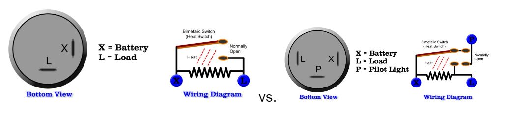
Caption: Two Prong Automotive Flasher vs. Three Prong Automotive Flasher
Source: http://www.gtsparkplugs.com/flashers-turn-signal.html
The mechanism that cancels the turn signal when you finish turning
Most cars have a turn signal shutoff function. Once you rotate the steering wheel to the left, the blinker turns off, and the lever returns to its previous position.
There’s a notched hub on the drive shaft (which spins as you turn the wheel). Hub has four notches. When the hazard lights are on, a lever pushes these notches, and the lever’s black tip engages the hub’s notches.
A spring-loaded roller holds the turn-signal stalk in place when you signal a right turn. Simultaneously, a plastic lever pushes the hub. As the hub rotates clockwise, notches hit the silicone lever, which rocks to allow them to pass. When the wheel turns left, the hub revolves counterclockwise, pulling the plastic lever. That dislodges the spring-loaded roller from the switch housing, resetting the stalk.
Symptoms of a Bad Turn Signal Relay
Here are a few symptoms of a bad turn signal relay.
- The flasher is broken, and the lights won’t work properly
- Turn signals are still; instead of blinking
- Additional lights are not working properly
- Parking lights are not working due to a bad circuit
- The flashing is either slow or rapid.
How to Test a Turn Signal Relay
You can do some jobs to make sure whether it is the relay that causes the problem.
Swap the Relay
You can swap the relays if the part numbers are the same. The turn signal relay is defective if the symptom spreads to other parts of your car. It’s the simplest and most reliable technique to diagnose a malfunctioning turn signal relay.
The 6 Volt Test
To replace the relay in your car with a six-volt battery, all you have to do is take it out. Plug the six-volt battery into the two terminals to hear a click. Listen for the relay to “click over” before assuming it is functioning properly. But if you can’t hear the relay “click over,” it’s time to get a new one.
It’s important to remember that this isn’t a failsafe method. Therefore if you have a multimeter, you should move on to the next test.
How to Wire a Turn Signal Flasher: Checking for Resistance
Connect the appropriate ends of your multimeter and switch it to the resistance measurement mode. The resistance must be between 50 and 120 ohms for a relay to operate properly. It should be replaced if a relay’s resistance reading is too high or registers as an abnormal value.
Remember that if the relay has no resistance, it is probably trapped in the closed position and needs to be replaced.
How to Wire a Turn Signal Flasher: Replacement of a Faulty Turn Signal Relay
As you discover that the relays are not working properly, you will replace them with new ones. For that, you can either do it yourself or go to a certified mechanic.
How to Wire a Turn Signal Flasher: Replacing the parts on your own
For replacing parts on your own,
- First, you will purchase a new turn signal relay matching your old one.
- Locate the position of the relay in the automobile via its manual and remove the old turn relay from it.
- Now, fix the new relay and check if it is working properly.
How to Wire a Turn Signal Flasher: Taking the car to a certified mechanic
If you are not confident enough to change the relay, you can always consult a certified mechanic for the work. They can help you in diagnosing the problem correctly and repair the car within a short time.
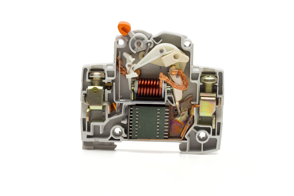
Caption: A simple relay
How to Wire a Turn Signal Flasher: Further Troubleshooting
Sometimes, changing the relays does not solve the problem, and for that, you can always troubleshoot your system. Here’s how you can do it
- Check the connections and plug and unplug each one at a time. This simple act can improve the flow of current.
- Check random fuses because they may be the reason for the wrong circuit.
- Look for insufficient grounds, as they can also be the culprit behind turn signal malfunctioning.
- Check the signal flasher relay harness.
Conclusion
It’s not hard to fix the relay that controls your turn signals. You can accomplish it independently if you have the necessary information and equipment. But if you’re not sure about the problem, you may always hire a professional mechanic. Here at cloom, we offer wiring harnesses and cable assemblies to ensure your connection.